Using Phasor Diagrams to Evaluate Series and True Parallel RLC AC

Draw The Phasor Diagram Of Series Rl Circuit

Phasor rlc impedance fasor sirkuit rangkaian seri Why is the inductive reactance or capacitive reactance phasor on the

Phasor rlc parallel series ac circuits diagrams using true Rlc series circuit Using phasor diagrams to evaluate series and true parallel rlc ac
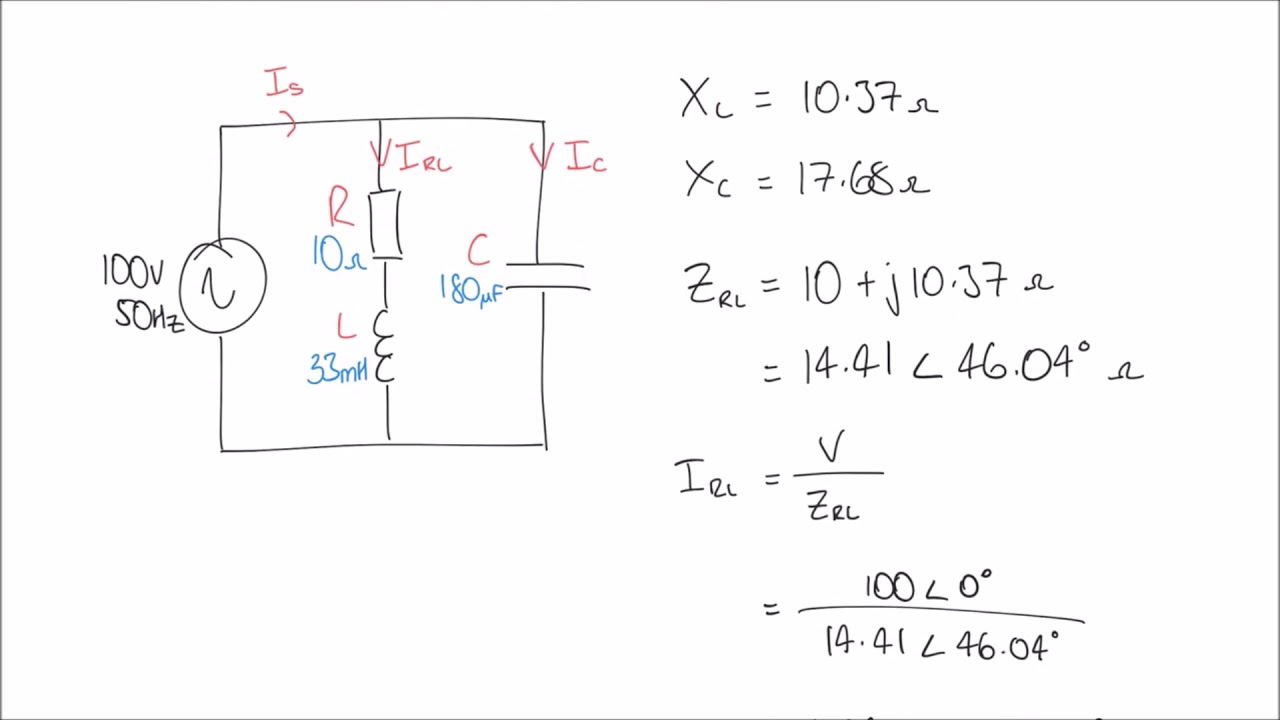
RL Series Circuit

Series phasor diagram rc circuit draw phase circuits power ckt voltages curve steps across

What is rc series circuit? phasor diagram and power curve

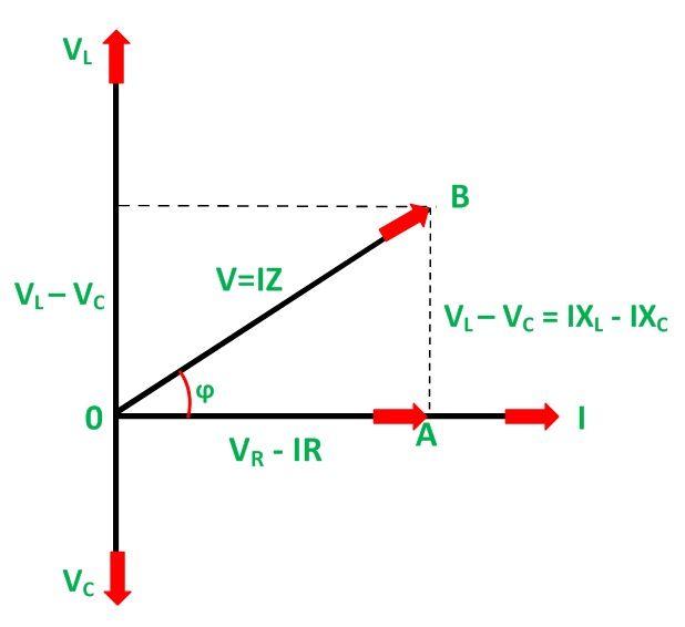
Circuit phasor series rlc inductive reactance diagram voltage capacitive parallel analysis impedance vector reference source axis electrical imaginary why powerPhasor rl rlc inductor capacitor voltage resistor electrical4u Rl series circuitRl series circuit.

Rl circuit diagram phasor series vector impedance voltage phase angle analysis triangle transformer current draw electrical4u voltages inductor example idealCircuit rl phasor derivation circuitglobe impedance diagrams Rl circuit : derivation, phasor diagram, impedance & its uses.

RL Series Circuit
RL Series Circuit

Using Phasor Diagrams to Evaluate Series and True Parallel RLC AC

RL Circuit : Derivation, Phasor Diagram, Impedance & Its Uses

RL Series Circuit - LEKULE BLOG

Why is the inductive reactance or capacitive reactance phasor on the

What is RC Series Circuit? Phasor Diagram and Power Curve - Circuit Globe

RLC Series Circuit - electrical and electronics technology degree